
July 18, 2025
An Introduction to Single Screw Extruders
Explore the basics of single screw extruders—how they work, core components, advantages, and common manufacturing applications.
7th August 2018
If you take a bolt, having a nut on it, and revolve the bolt, in a fixed axis, both the bolt and the nut revolve. Then, if you hold the nut with a wrench, and revolve the bolt, in the proper direction, the nut will travel forward and fall off the end of the bolt.
A clay auger works in a similar manner. Inside of the closed auger barrel there is a “clay nut” which moves forward on the screw. The clay nut is ephemeral. The clay nut is constantly being destroyed by passing off the end of the auger, and it is constantly being reformed by feed material entering the closed auger barrel from the feed hopper, or vacuum chamber.
Note that with the nut and bolt, if the nut revolves in the same direction as the bolt, but at a lower rate of rotation than rotation of the bolt, it will eventually drop off the end of the bolt.
The “clay nut” on an extrusion auger cannot be held by a wrench, or any means whereby it will not have some rotation in the same direction as the auger is rotating. Its tendency to revolve with the auger is retarded by adherence to the inner surface of the barrel which surrounds the auger. The effect of this adherence varies between different clays and different tempering of the same clay. Therefore, a clay auger efficiency (volumetrically) varies and is never 100% of the theoretical volumetric capacity of the auger.
Extruder designers and operators recognize this adherence factor and generally attack it by design of the inner surface of the auger barrels which are ribbed, fluted, checkered, corrugated, or have some other design. In many cases they are over zealous in this respect. Seldom is any attention given to other factors which would retard rotation with the auger such as the “angle of side slip” (which will be discussed later) or to the ratio of the area of adherence surface to the volume of material, between the auger lands and under the adherence surface. In Europe when extruding very soft tempered clays, having little abrasion and low adherence values, broken flight augers and pin barrels are used; but the pin barrel is not feasible on stiff tempered, abrasive materials.
The coefficient of sliding friction is an important factor in an auger’s performance. Referring again to the bolt and the nut, it is obvious that in moving forward along the revolving bolt the intruding lands (or threads) of the nut must slip or slide over the surfaces of the protruding lands (or threads) on the bolt. If the bolt and nut are rusty much power input will be necessary to turn the bolt; but if the threads are well polished or oiled, little power will be required to turn the bolt.
The coefficient of sliding friction between the material on the clay nut and the metal from which the auger is made varies greatly from clay to clay and under different operating conditions. Some clays contain natural internal lubricants and slide easily over the surfaces of the auger lands. Some clays are doped with additives to decrease the coefficient of sliding friction. Some clays are sticky and resist sliding over the wings of the auger. On most clays (except some “sticky” clays) as the percentage of tempering water is reducer, the coefficient of sliding friction rises, and the current trend is to run stiffer columns than formerly. Most designers and machine operators recognize that a polished auger performs better, but often neglect the other factors in sliding friction, which are rather hard to pin down.
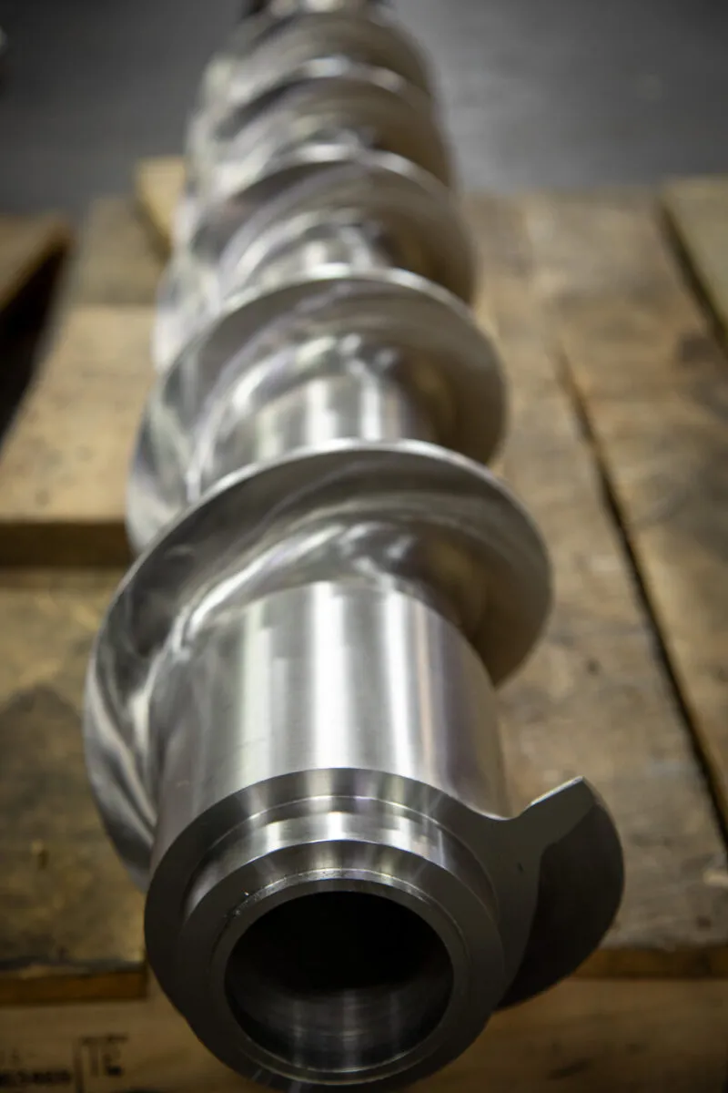
Figure 1 illustrates an auger for the extrusion of clay.
An auger or screw has been described as “an inclined plane wound around a cylinder.” This definition is descriptive but it is an oversimplification. An inclined place has a uniform angle of pitch or slop across the plane. On the other hand the continuous flight of an auger’s lands or wings has a dual angle or pitch of slope. The duality of angles or pitch become apparent when the helix angles are analyzed.
The tangent of the helix angle, at any point in an auger’s land, is the “pitch divided by the circumference at that particular point.” The “mean helix angle” of an auger or screw is calculated for the diameter half-way out of the land from the hub. The mean helix angle is the “average” slope of the land. However, the helix angle or slope is less at a point on the perimeter of the auger land, and greater at the base of the land where it joins the hub of the auger.
For example, consider and auger that is 16” in diameter, having a 12” pitch (3/4 pitch) and the hub of which is 7” in diameter. By the above formula the “mean helix angle: of this auger is 18.36 degrees but:
The forward slope of the auger’s land averages 18.36 degrees and moves the material generally forward. At the same time the 15.2 degree slope of “slide-slip” pushes or rolls the material outwardly, from the hub, and against the inner surface of the auger barrel, which increases the adherence value of the clay nut to the inner surface of the auger barrel.
By design of the auger’s lands (wings) the effect of the angle of “slide-slip” can be changed; both as to effect on “adherence to the auger barrel” and as to the “coefficient of sliding friction.”
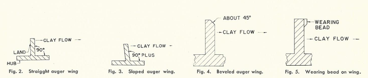
A conventional auger wing is “straight-up.” See Fig. 2.
The pressure of “adherence” against the inner surface of the auger barrel can be increased; and the coefficient of sliding friction can be decreased by use of a “slope-back” land (wing). See Fig. 3. Due to their design some augers when newly installed in a brick or tile machine, start off at a low rate of production, on some types of clay. This loss of production many continue for several days. There are “tricks” in all trades. Following is a foreman’s “trick” for use on augers that start off at low production when new: the front edge of the wing is ground off at approximately a 45 degree angle. This increases “adherence” value against the inside of the auger barrel: and at the same time decreases the total effect of friction between the clay “nut” and the metal in the auger wing (see Fig. 4). Some clays, if not tempered to stiff, have a very low coefficient of sliding friction and a good “adherence value.” A “wearing bead” can be added to the forward edge of the auger wings used for extruding this kind of clay. However, it should be adopted with care. On hard running clays, tempered rather stiff, this “wearing bead” may stop production completely. It tends to increase the total effect of the coefficient of sliding friction and decrease the effect of the angle of “slide-slip” which lowers adherence pressure against the inside of the auger barrel. It may produce excessive heating of the clay, the auger, and the auger barrel. See Fig. 5.
When you shorten the pitch of the lands on an auger, you increase the mechanical advantage of the auger. This theory is well known but its application is often disappointing. When you shorten the pitch of an auger (of a given diameter) you increase the effective coefficient of sliding friction, at the same time, which is detrimental. When the pitch is shortened the helix angle are reduce, i.e., the forward slope of the auger lands is flatter, and the slope is lessened. The clay nut will not slide over the flatter slope as easily as it will over a steeper slope. In addition the angle of “slide-slip” is lessened and its contribution to “adherence” of the clay nut to the inside of the auger barrel is lessened.
The actual mechanical advantage of a machine cannot be calculated with exactness since there are too many uncertainties involved. On the other hand the theoretical mechanical advantage can be calculated exactly, since friction is assumed to be absent.
As pitch of an auger is increased (which also increases the helix angle of the wings) the efficiency of the auger increases. Kimball and Barr show that efficiency drops quickly, with decreases of helix angles of power screws, when the coefficient of sliding friction is high, than when it is low. However, in all cases efficiency drops rapidly when the helix angle are below 10 degrees.
The efficiency of any auger decreases when the temper of the clay is stiffened. Present tendency is to stiffer and stiffer columns and therefore it is apparent that the pitch (and helix angle) should be increased in order to insure efficiency.
Modern augers which are designed with special details for plastics have several distinctive special details. A plastic auger has a length of around 20 to 24 times the diameter of the auger. A 6” diameter auger would be 10 or 12 ft. long. It has three zones. The feed section, the compression zone, and a metering section. On a 6” diameter auger the depth of the lands or wings is only .50” in the feeding zone and in the compression zone and metering zone lands are only .125” deep. The pitch is 1 to 1, and the helix angle would be about 20 degrees. The auger is detailed to compress the material highly.
It is not adaptable to ceramic bodies but its worthy of examination because of contrast. A clay is not a true plastic but is a “quasi-plastic” which has both plastic and solid characteristics. In a clay, factors other than “true plasticity” are involved.
The auger was first used in the ceramic industry to extrude soft tempered, loosely prepared, surface clays; or to extruder soft filter cake high in moisture. Compression was desirable. It was secured by shortening the pitch of the auger toward the exit, or die end of the auger, or by tapering the auger so that the small diameter end was at the exit end of the auger, and often by both.
July 18, 2025
Explore the basics of single screw extruders—how they work, core components, advantages, and common manufacturing applications.
September 27, 2024
The Bonnot Company has manufactured a line of extruders for processing butyl/mastic rubbers (butyl) since the 1950's. The company recognized the need to offer processing extruders for this rapidly developing market. In keeping with a core principle of continuous improvement, these designs have evolved over time to remain the pre-eminent industry choice for butyl processing equipment/extruders.
September 19, 2024
The Bonnot Company has a variety of custom extruders designed for bulk feeding of rubbers, both natural and synthetic, silicones, butyls and mastics. Regardless of the batch size or material viscosity, there is a solution available. If one of the company's standard designs does not meet your needs, a custom solution is developed. Customized solutions specifically tailored to a customer's needs are a core competency of ours and competitive advantage.